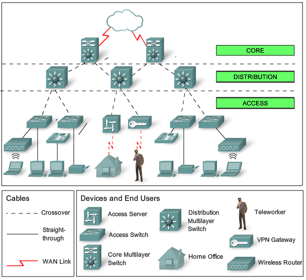
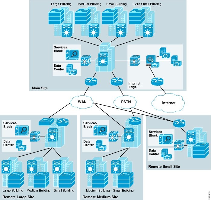
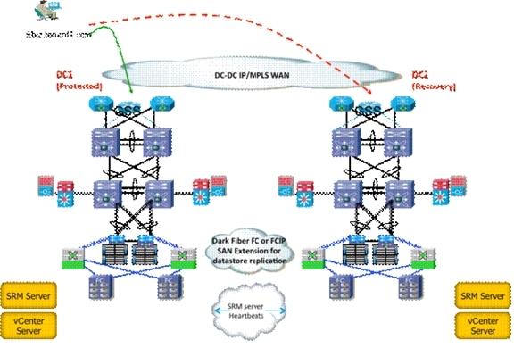
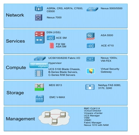
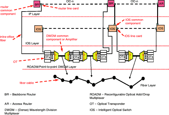
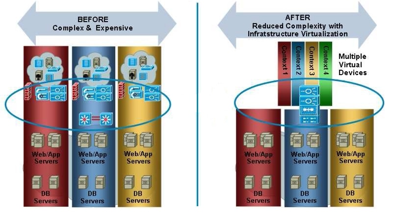
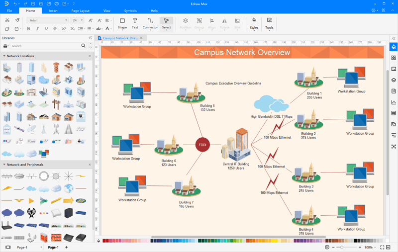
The core layer is a high speed switching backbone and should be designed to switch packets as fast as.
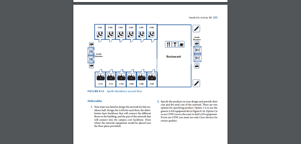
Design the lans for each floor the distribution layer backbone.
Room that contains the core switching environment.
The required maps for your design are listed below.
Specify where the network equipment would be placed use the floor plans provided.
Using the layer 3 access design removes the layer 2 to layer 3 boundary at the distribution layer and makes each access switch the boundary between the layer 2.
Physically a traditional network design would likely see these utp cables backhauled from the individual rooms to a comms.
In another approach to access and distribution layer design you can use layer 3 beyond just the core and distribution layers and configure layer 3 all the way into the access layer.
The backbone core layer that provides optimal transport between sites.
Function of the core layer.
Each of these distribution points then connect back to a central comms.
The local access layer that provides workgroup user access to the network.
Design the lans for each floor the distri bution layer backbone that will connect the different floors in the building and the part of the network that will connect into the campus core backbone.
Room on each floor acting as a distribution point.
Draw where the network equipment would be placed use the floor plans provided 2.
There is overlapping information in those 2 readings the 1st source will help you with a simplified review and a summary of network infrastructure design principles.
Design the lans for each floor the distribution layer backbone that will connect the different floors in the building and the part of the network that will connect into the campus core backbone.
The distribution layer that provides policy based connectivity.
Two main readings for this topic are an excerpt from cisco networking simplified and chapter 3 from the o reilly book.

